Elecraft KRX3 User Manual
Browse online or download User Manual for Accessories communication Elecraft KRX3. Elecraft KRX3 User Manual
- Page / 54
- Table of contents
- BOOKMARKS
- ELECRAFT 1
- Contents 2
- Introduction 3
- Customer Service and Support 4
- How ESD Damage Occurs 5
- Preventing ESD Damage 5
- WARNING 5
- Preparing for Installation 6
- Parts Included 7
- KRX3 Hardware Bag E850334 8
- E850344 TMP-BNC Cable Bag 9
- Installation Procedure 11
- CAUTION 14
- Final Assembly 43
- Removing the KRX3 Module 44
- Operation 45
- Using the Sub Receiver 46
- Diversity Receive 47
- Tools Required 48
- Procedure 48
Summary of Contents
ELECRAFT K3 HIGH-PERFORMANCE 160 – 6 METER TRANSCEIVER KRX3 HIGH-PERFORMANCE SUBRECEIVER INSTALLATION AND OPERATION Rev. F1, March 14, 2014
10E850249 I.F. Crystal Filter Bag (or Box) NOTE: If the optional 8-pole 2.8K filter is purchased instead (see next item) this filter is not supplie
11Installation Procedure K3 KIT BUILDERS: If you were directed here to install the KRX3 Subreceiver as part of the initial K3 assembly, remove the
12If your K3 has the K144XV 2-meter option installed, remove the three 6-32 black flat head screws holding it to the left side panel (see Figure 4)
13Remove the screw shown in Figure 6. It is located directly behind the front panel microphone connector. There may be a lock washer under the scre
14 CAUTION Before continuing on with the next step, be sure you have removed the three top Front Panel Assembly screws shown in Figure 7. You may b
15With the three screws removed, the main DSP board is held on to the front panel board by two multi-pin connectors. Slip your finger tips between
16Mount the three standoffs on the component side of the main DSP board as shown in Figure 14. Be sure that: The standoffs are on the component
17 Locate resistor R3 on the front panel board (the board still mounted on the front panel assembly). If R3 is positioned above the board on its le
18Plug the aux DSP board into the main DSP board by mating P52 and P53 on the aux DSP board (at the narrow end) with J52 and J53 on the main DSP bo
19If R3 was positioned above the board on its leads, look between the DSP boards and the front panel board to verify that the leads are not touchin
2 Contents See Appendix A to install or change crystal filters in a previously assembled KRX3 Introduction ...
20Hold the front panel in place against the chassis assembly and turn the unit over to look at the two multi-pin connectors on the top of the RF bo
21Checking and Modifying Resistor R91 and DAC Input Circuits The value of resistor R91 must be 22 ohms. Perform the following procedure to check th
22Installing the KRX3 Module Supports Install two standoffs on the K3 RF board (the large board filling the bottom of the K3) as shown in Figure 24
23Installing the Auxiliary KSYN3 Synthesizer The KSYN3 is supplied with a stiff metal plate covering the front of the pc board. This plate keeps th
24Locate the four coaxial TMP cables supplied and sort them by length. There are two 5” (13 cm) one 10” (25 cm) and one 12” (30 cm) cables. These a
25Install the Auxiliary KSYN3 board on the back of the front panel shield between the KREF3 board and the side panel. Use the hardware exactly as s
26Auxiliary KRX3 Antenna Input (Optional) Normally, the KRX3 subreceiver will share whatever antenna is in use by the K3 main receiver. If you pla
27Route the cable across the back of the K3. When the KRX3 module is installed, it will connect to the KRX3 at a point directly in front of the KIO
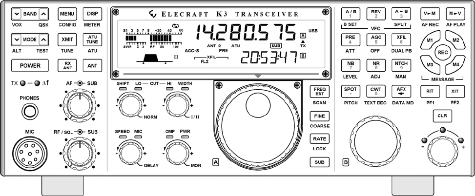
28Remove the screw holding the KANT3 (or, if installed, the optional KAT3) board to the standoff and the screw holding the 2D fastener to the rear
29Check the BNC-TMP cable assembly to see if the nut and lock washer are already threaded onto the BNC connector. If so, remove them completely, wo
3Introduction If your KRX3 is already installed in your K3, turn to Using the Sub Receiver on page 46 for operating instructions. The KRX3 subrec
30Mount the solder lug attached to the braid as shown in Figure 34, using a 4-40 3/8” (9.5 MM) black pan head screw, #4 inside tooth lock washer an
31Replace the 4-40, 3/16” (4.8 mm) black flat head screw that secures the back panel to the 2D fastener as shown in Figure 31. Replace the two 4-4
32Install four standoffs on the KRX3 main circuit board as shown in Figure 37. Be careful to use the correct length standoff and the exact combinat
33 Enter the FREQ OFFSET shown on each filter. The optional 8-pole filters have no offset marked on them. Enter a zero in the FREQ OFFSET column fo
34Mount the Mixer and KNB3 boards on the main KRX3 board as shown in Figure 39. Be certain the connector on each board is properly aligned and mate
35If you have the KPBF3 option, install the board now with 4-40 1/4” (6.4 mm) pan head screws and #4 split lock washers as shown in Figure 41. Thes
36Place a 7/8” (22 mm) unthreaded sleeve over each of the long screws so they rest against the top of the circuit board (see Figure 42), then place
37Place the battery cover on BT1 on the K3 RF board as shown in Figure 44. Hint: gently squeeze the narrow ends of the cover to make the sides bow
38Plug the SUBIN interface board into J64A on the K3 RF board as shown in Figure 46. J64A is directly in front of the KIO3 board in the rear left c
39Position the TMP cables so they will be out of the way when you install the KRX3 module. Figure 48 shows a suggested arrangement. The exact cable
4Customer Service and Support Technical Assistance You can send e-mail to [email protected] and we will respond quickly - typically the same d
40Hold the assembled KRX3 module directly over the K3 and attach the TMP cables to J82 and J85 on the module as shown in Figure 49. Figure 49. TM
41If installed, attach the antenna cable connected to either the KAT3 or to the AUX RF BNC jack on the rear panel to J92 at the end of the KRX3 as
42Secure the KRX3 module to the two standoffs using 1-1/2” (38 mm) 4-40 pan head screws as shown in Figure 51. The screws will pass through the int
43 Final Assembly Remove the covering over the self-adhesive side of the foam pad and press the adhesive side against the speaker magnetic shield (
44Position the top cover on the K3. Note that the tab on the back center goes under the rear lip of the K3 rear panel. Secure the top cover with th
45Operation Preparing for Operation If you installed the KRX3 subreceiver yourself, you must complete the following before you can operate the subr
46Using the Sub Receiver The KRX3 option adds an independent, high-performance sub receiver to the K3. It allows you to monitor a second frequency
47receiver signal loss in this case, use the sub receiver’s AUX input. When the main and sub receivers are used on separate bands, some additiona
A-1 Appendix A: Installing Crystal Filters in the KRX3 Subreceiver The crystal (roofing) filters in the KRX3 subreceiver are contained in the L-shap
A-2 Observe ESD precautions when working inside your K3. Wear an ESD wrist strap or frequently touch an unpainted metal ground while working. Remove
5Preventing Electrostatic Discharge Damage There is no climate or work location where the components of your K3 are safe from Electrostatic Dischar
A-3 Remove the KRX3 RF module as follows. The circled numbers refer to Figure A-4 below. Remove the two long screws that attach the KRX3 enclosur
A-4 Remove the RF board from the lower half of the enclosure as follows (see Figure A-5): Remove the two sleeves from the long screws. If the KBPF3
A-5 Important: The information recorded in the next step is required to enable your filters after reassembling your K3. Record the data in the table
A-6 CAUTION 1) Do not use screws longer than 1/4” (6.4 mm) to mount the filters. Longer screws may extend into the optional 8-pole filter and dest
A-7 If you removed the KBPF3 board, replace it. Be sure the three connectors are aligned so all the pins engage. The connectors are visible from the
6We strongly recommend you take the following anti-static precautions (listed in order of importance) to avoid trouble: Leave ESD-sensitive part
7Parts Included The following parts should be included in your kit. Check to ensure you have them all. If any parts are damaged or missing, contact
8ILLUSTRATION DESCRIPTION QTY. ELECRAFT PART NO. KNB3 SUBIN Board ESD Sensitive. 1 E850331 KNB3 SUBOUT Board 1 E850332 KRX3 Enclosure, Top
9ILLUSTRATION DESCRIPTION QTY. ELECRAFT PART NO. Standoff, Hex Male/Female, 7/16” (11mm) 3 E700017 Unthreaded Sleeve Spacer, 7/8” (22 mm) 2 E
Related products and manuals for Accessories communication Elecraft KRX3
 (1 pages)
© 2020, manymanuals.com. All rights reserved. | 1.568 s |
 Manymanuals.com
 Manymanuals.de
 Manymanuals.fr
 Manymanuals.it
 Manymanuals.pl
 Manymanuals.cz
 Manymanuals.es
 Manymanuals-pt.com
Comments to this Manuals